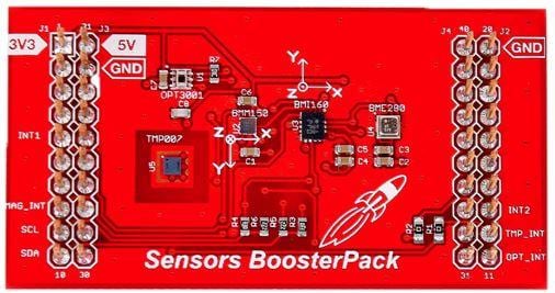
From the datasheet and it's Guide Manual http://www.ti.com/lit/ug/slau666b/slau666b.pdf
BME280 has a slave address: 0x77;
To control it we need to config several register as below:
Control Humidity Register (ADDR: 0xF2) Default 0x00 not activate
Control Measure Register (ADDR: 0xF4) Default 0x00 not activate
b[7:5]: control temperature measurement
b[4:2]: control pressure measurement
b[1-0]: Control IC mode
00: sleep mode
01,10: force mode
11: normal mode
Control filter Register (ADDR: 0xF5) Default 0x00
b[7:5]: control standby time
b[4:2]: control IRR filter
b[0] : config SPI in 3 wires ('1') /4 wires ('1')
default ID: ADDR: 0xD0 Value: 0x60 (96)
This example to test read humidity from IC
Setup I2C in CC2640:
int32_t hum;
uint16_t adc_H;
uint8_t id;
//uint8_t pow;
uint8_t txBuffer[2]; //BME280 require ADDR Register>> Command Register
uint8_t rxBuffer[8];
I2C_Handle i2c;
I2C_Params i2cParams;
I2C_Transaction i2cTransaction;
I2C_init();
I2C_Params_init(&i2cParams);
i2cParams.bitRate = I2C_400kHz;
i2c = I2C_open(Board_I2C_TMP, &i2cParams);
if (i2c == NULL) {
Display_printf(display, 0, 0, "Error Initializing I2C\n");
while (1);
}
else {
Display_printf(display, 0, 0, "I2C Initialized!\n");
}
Config control register
/* Common I2C transaction setup */i2cTransaction.writeBuf = txBuffer;
i2cTransaction.writeCount = 1;
i2cTransaction.readBuf = rxBuffer;
i2cTransaction.readCount = 1;
i2cTransaction.slaveAddress = BME280_ADDR;
//READ ID device
txBuffer[0] = 0xD0;
if (I2C_transfer(i2c, &i2cTransaction))
{
//light = (rxBuffer[0] << 8) | (rxBuffer[1]);
id = rxBuffer[0];
Display_printf(display, 0, 0, "Device ID: %d (C)",
id);
}
// Configuration for measuring
i2cTransaction.writeCount = 2;
txBuffer[0] = 0xF5;
// |b7 |b6 |b5 |b4 |b3 |b2 |b1 |b0 |
// | time to sleep |filter |not |'1':SPI 3,'0':SPI 4|
txBuffer[1] = 0x2C; //0x2Ct_sb = 62.5ms,filter = 011 see p.30 of data sheet
//txBuffer[2] = 0x10;
if (I2C_transfer(i2c, &i2cTransaction))
{
//light = (rxBuffer[0] << 8) | (rxBuffer[1]);
id = rxBuffer[0];
Display_printf(display, 0, 0, "Measure After Configuration : %d (C)",
id);
}
// Configuration hum measure:
i2cTransaction.writeCount = 2;
txBuffer[0] = 0xF2;
txBuffer[1] = 0x03; //00: skip, 01: oversamplingx1, 10: oversamplingx2
//txBuffer[2] = 0x10;
if (I2C_transfer(i2c, &i2cTransaction))
{
//light = (rxBuffer[0] << 8) | (rxBuffer[1]);
id = rxBuffer[0];
Display_printf(display, 0, 0, "Hum register After Configuration : %d (C)",
id);
}
// Configuration MODE 00: sleep, 01,10: Force, 11: Normal
i2cTransaction.writeCount = 2;
txBuffer[0] = 0xF4;
txBuffer[1] = 0x03; //t_sb = 10ms,filter = 2 see p.30 of datashhet
//txBuffer[2] = 0x10;
if (I2C_transfer(i2c, &i2cTransaction))
{
//light = (rxBuffer[0] << 8) | (rxBuffer[1]);
id = rxBuffer[0];
Display_printf(display, 0, 0, "Mode After Configuration : %d (C)",
id);
}
/* Read Calib coefficient of Humidity*/
// READ dig_H1
i2cTransaction.writeCount = 1;
txBuffer[0] = 0xA1;
if (I2C_transfer(i2c, &i2cTransaction))
{
dig_H1 = rxBuffer[0];
Display_printf(display, 0, 0, "Coefficient dig_H1 : %u (C)",
dig_H1);
}
//READ dig_H2 - digH6
txBuffer[0] = 0xE1;
i2cTransaction.readCount = 7;
if (I2C_transfer(i2c, &i2cTransaction))
{
dig_H2 = ((rxBuffer[1]<<8)|rxBuffer[0]);
Display_printf(display, 0, 0, "Coefficient dig_H2 : %d (C)",
dig_H2);
dig_H3 = rxBuffer[2];
Display_printf(display, 0, 0, "Coefficient dig_H3 : %u (C)",
dig_H3);
dig_H4 = ((rxBuffer[3]<<4)|(0x0F&rxBuffer[4]));
Display_printf(display, 0, 0, "Coefficient dig_H4 : %d (C)",
dig_H4);
dig_H5 = ((rxBuffer[5]<<4)|((0xF0&rxBuffer[4])>>4));
Display_printf(display, 0, 0, "Coefficient dig_H5 : %d (C)",
dig_H5);
dig_H6 = rxBuffer[6];
Display_printf(display, 0, 0, "Coefficient dig_H6 : %d (C)",
dig_H6);
}
/* Take 20 samples and print them out onto the console */
//i2cTransaction.writeBuf = txBuffer;
i2cTransaction.writeCount = 1;
//i2cTransaction.readBuf = rxBuffer;
i2cTransaction.readCount = 2;
txBuffer[0] = 0xFD;
for (sample = 0; sample < 20; sample++) {
if (I2C_transfer(i2c, &i2cTransaction)) {
/*
* Extract degrees C from the received data;
* see TMP116/006 datasheet
*/
//temperature = (rxBuffer[0] << 8) | (rxBuffer[1]);
//temperature *= 0.0078125;
/*
* If the MSB is set '1', then we have a 2's complement
* negative value which needs to be sign extended
*/
//if (rxBuffer[0] & 0x80) {
// temperature |= 0xF000;
//display ambient level light
/*
pow = (rxBuffer[0] >> 4) ;
light = ((rxBuffer[0]&0x0F) << 8) | (rxBuffer[1]);
while(pow!=0)
{
pow -=1; // Multiply 2^n by left shifting to n times
light <<=1;
}
light *=0.01;
*/
adc_H = ((rxBuffer[0] << 8) | (rxBuffer[1]));
hum = bme280_compensate_H_int32((int32_t)adc_H);
hum >>=10;
Display_printf(display, 0, 0, "Sample %u: %d (%c)",
sample, hum,'%'); //temperature
}
else {
Display_printf(display, 0, 0, "I2C Bus fault.");
}
/* Sleep for 1 second */
sleep(1);
}
I2C_close(i2c);
Display_printf(display, 0, 0, "I2C closed!");
return (NULL);
}
When we read from I2C we got a raw value of humidity from two Register 0xFD (High Byte) 0xFE(Low Byte). The value will transfer to rxbuffer[0] and rxbuffer[1] respectively.
Next, we need to convert to real value using a compensation function as describe in P25-P26 of the datasheet
Next, we need to convert to real value using a compensation function as describe in P25-P26 of the datasheet
uint32_t bme280_compensate_H_int32(int32_t adc_H)
{
int32_t v_x1_u32r;
v_x1_u32r = t_fine - ((int32_t)76800);
v_x1_u32r = (((((adc_H << 14) - (((int32_t)dig_H4) << 20) - (((int32_t)dig_H5) *
v_x1_u32r))+ ((int32_t)16384)) >> 15) * (((((((v_x1_u32r*
((int32_t)dig_H6)) >> 10) * (((v_x1_u32r * ((int32_t)dig_H3)) >> 11) +
((int32_t)32768))) >> 10) + ((int32_t)2097152)) * ((int32_t)dig_H2) +
8192) >> 14));
v_x1_u32r = (v_x1_u32r - (((((v_x1_u32r >> 15) * (v_x1_u32r >> 15)) >> 7) *
((int32_t)dig_H1)) >> 4 ));
v_x1_u32r = (v_x1_u32r < 0 ? 0 : v_x1_u32r);
v_x1_u32r = (v_x1_u32r > 419430400 ? 419430400 : v_x1_u32r);
return (uint32_t)(v_x1_u32r>>12);
}
Notice: The values of calibration are fixed and we can store some elsewhere to reuse rather than access it each time we want to use BME280 to read humidity value.
dig_H1 = 0
dig_H2 = 379
dig_H3 = 0
dig_H1 = 0
dig_H2 = 379
dig_H3 = 0
dig_H4 = 281
dig_H5 = 50
dig_h6 = 30

Comments
Post a Comment